Accessories and options
Accessories and options
We offer many accessories and options in our reducers depending on the working conditions.
Corrosion production classes

C2 (Standard)
Our standard paint class. It is suitable for both interior and exterior use with protection in areas with low humidity and contamination.

C3
Suitable for indoor and outdoor installations exposed to the elements, where humidity and chemical contamination are moderate.

C4
Suitable for indoor and outdoor installations exposed to the elements, where humidity and chemical contamination are generally high.

C5
Suitable for indoor and outdoor installations exposed to the elements where humidity and chemical contamination are constantly high.
Types of oil

Mineral oils
Our units use oils with ISO VG viscosity grades 220, 320, and 460. These are generally recommended for temperatures above zero and up to 40 degrees Celsius. The mineral lubricant should be changed every 10,000 hours.

Synthetic oils
They are recommended for both higher and lower ambient temperatures than mineral oils because their viscosity changes only slightly with temperature. A change interval of 25,000 hours is recommended between ambient temperatures of -25°C and 40°C.

Food-grade oils
These oils are recommended for gearboxes operating on food production lines, where oil may accidentally mix with products. They meet NSF H1 standards.

Biodegradable
They are as environmentally friendly as possible thanks to their highly soluble properties. They comply with the CEC-L-33-A-93 test standard, which defines a maximum biological solubility of 21 days.

-40˚ Ambient oils
Special synthetic oils of ISO VG 150 and 220 viscosity are recommended for gearboxes operating in ambient temperature conditions of -25°C.
sealing options
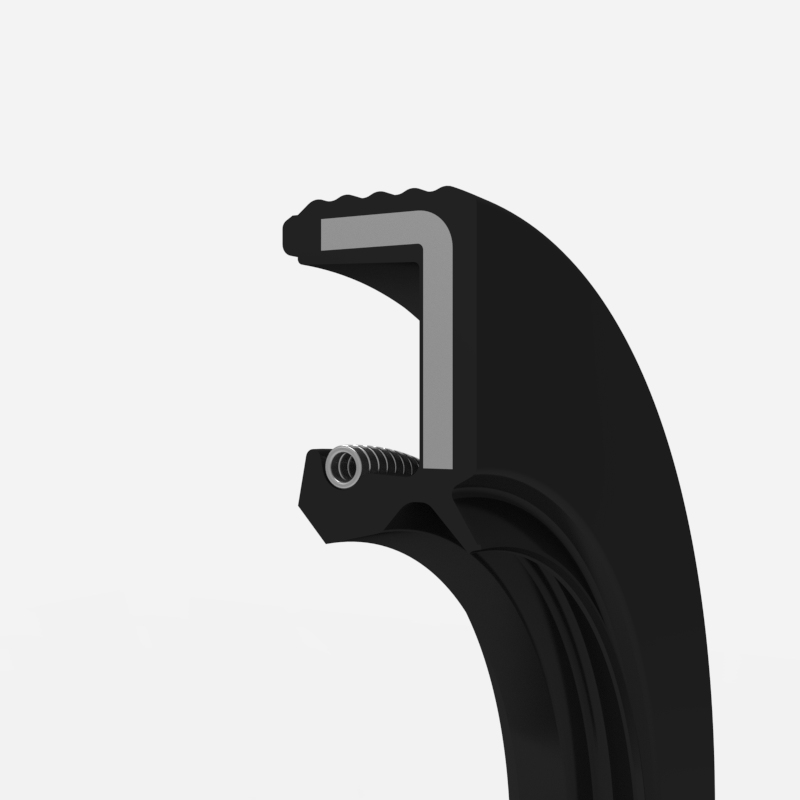
Nitrile (NBR) seals
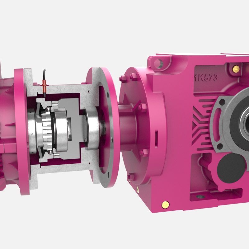
Nitrile seals are suitable for low-speed shafts. Their operating temperatures range from -40°C to +100°C. We use nitrile seals with a dust lip on the output shafts of our gearboxes.
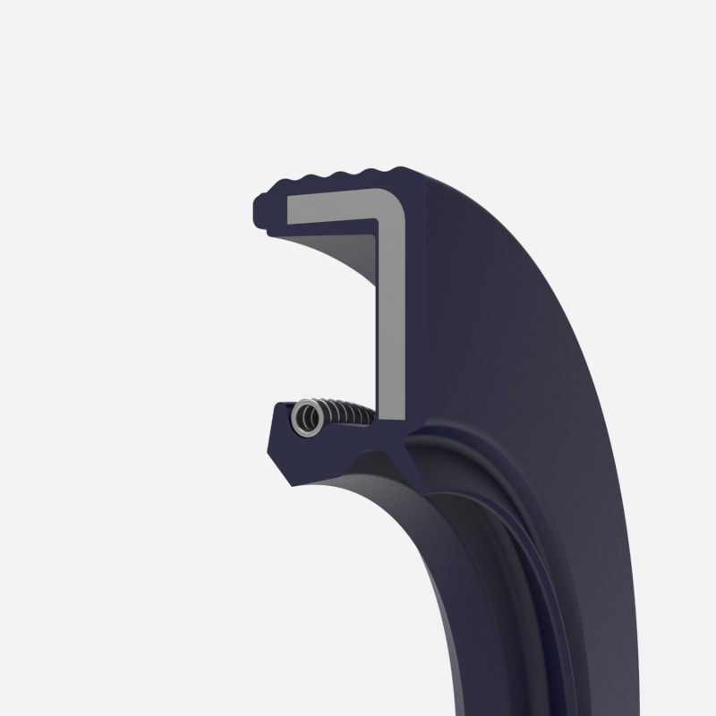
Viton (FKM) gaskets
These seals are made from a carbon-based material and are used on high-speed shafts. They are suitable for operating temperatures from -25°C to +160°C. We use Viton seals on our input shafts.
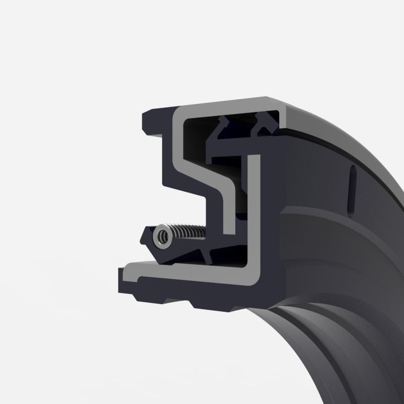
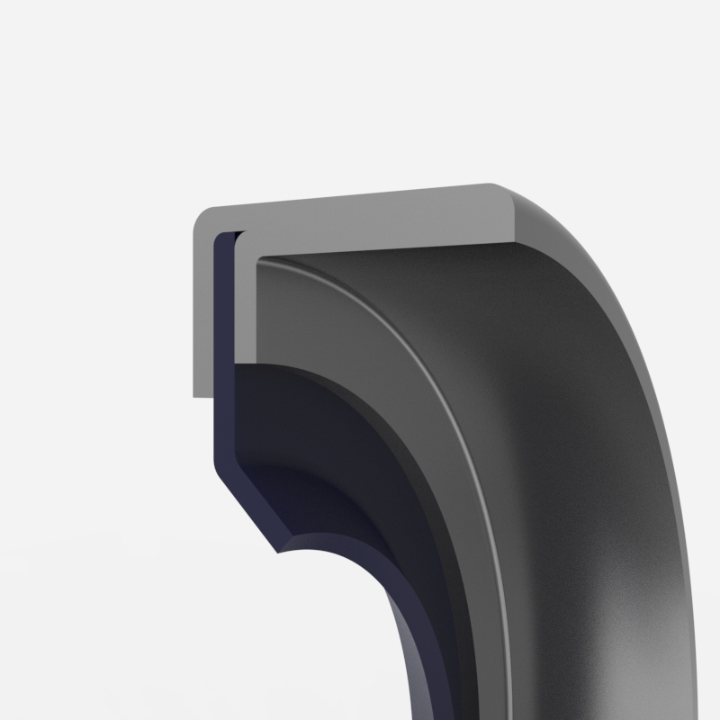
Cassette seals (FKM, NBR)
These are specially designed seals made from FKM and NBR materials. They are primarily used in corrosive environments to prevent corrosive materials from entering the gearbox. We use these seals on low-speed shafts.
Application of labyrinth seals
Various protection techniques are applied to joints that operate in very dusty environments.
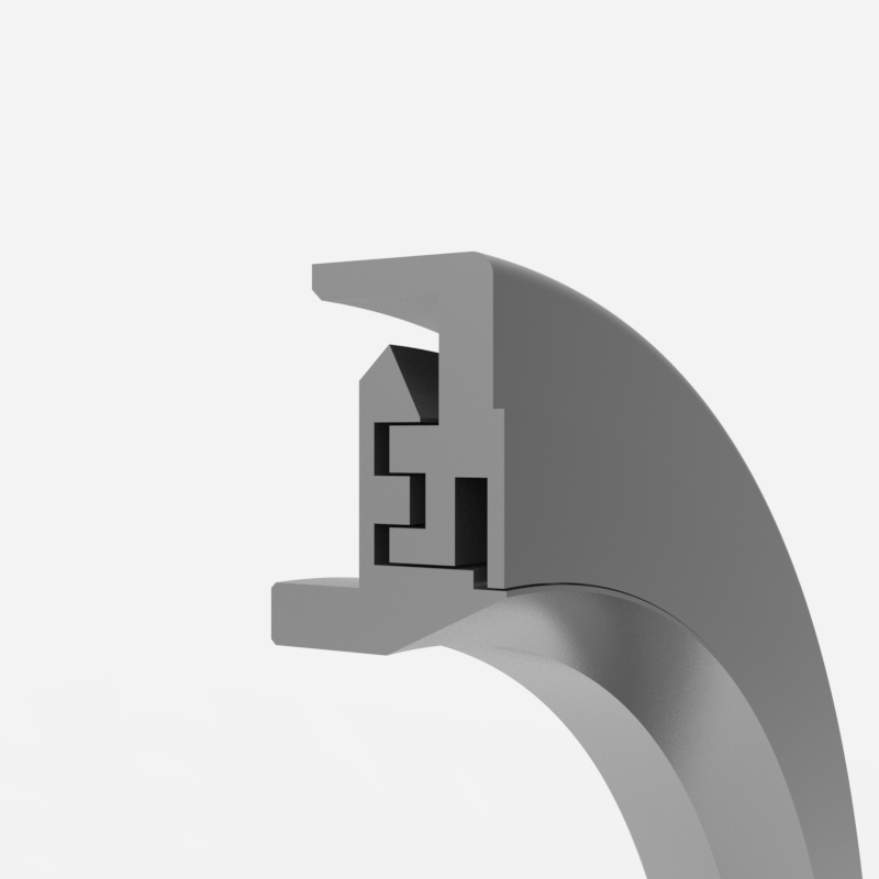
PTFE seal
The seals are made of polytetrafluoroethylene, a material with a low coefficient of friction and high resistance to chemical environments. They can operate between -80°C and +200°C. They are suitable for chemical working conditions.
Taconite Sealing Application
Labyrinth seals are suitable for very dusty and corrosive working environments. They are generally fitted with an additional scraping system.
Lubrication options
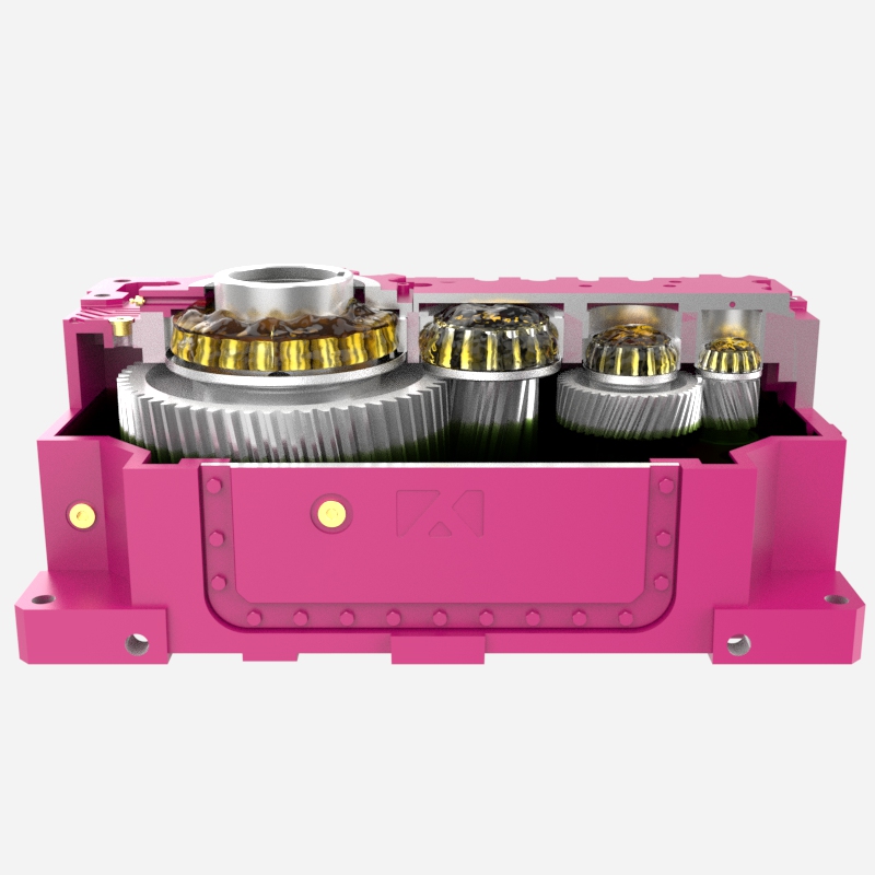
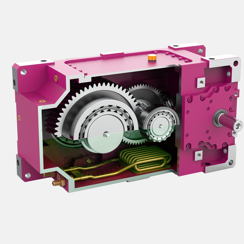
Oil bath lubrication
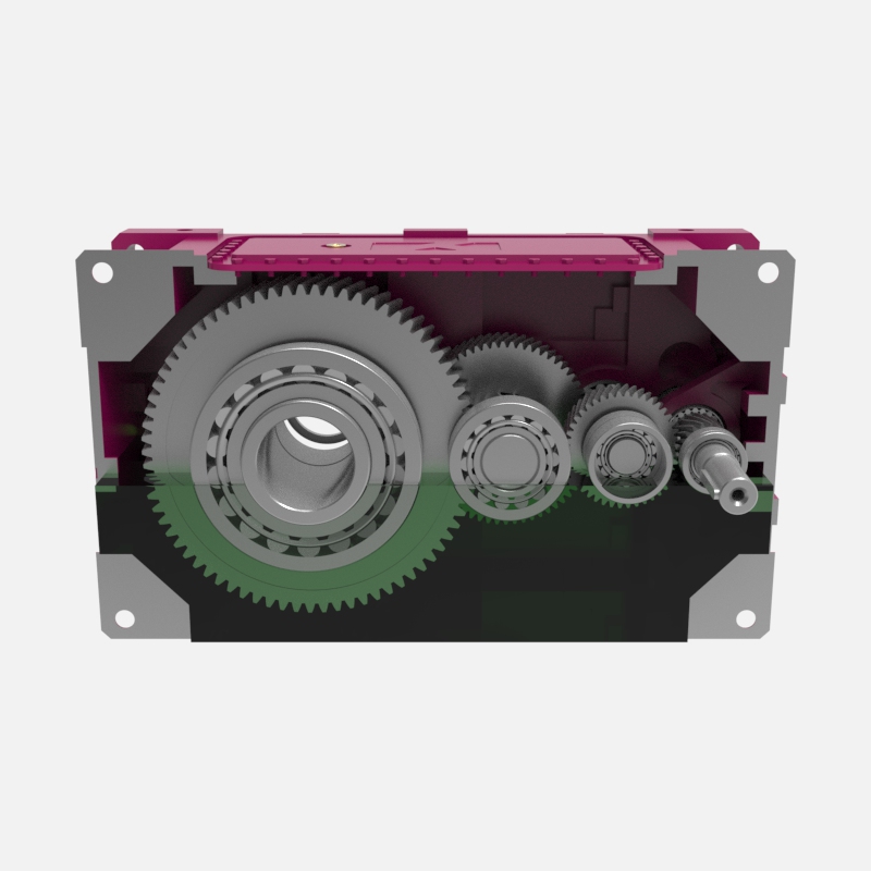
Lubrication system without additional equipment. All internal parts (gears, bearings and seals) are lubricated by splash lubrication or directly.
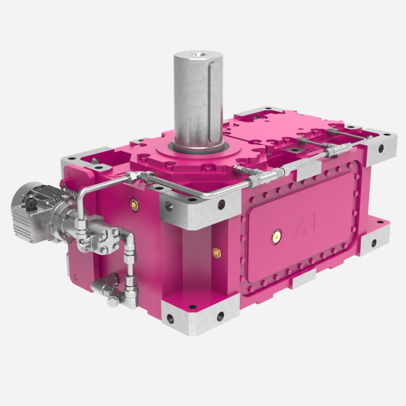
Forced lubrication
Particularly in industrial gearboxes, the upper bearings cannot receive oil via a lubrication bath when operating in certain mounting positions. To lubricate these bearings, oil from the lower levels is pumped directly to the bearing. This significantly increases efficiency due to reduced churning losses.
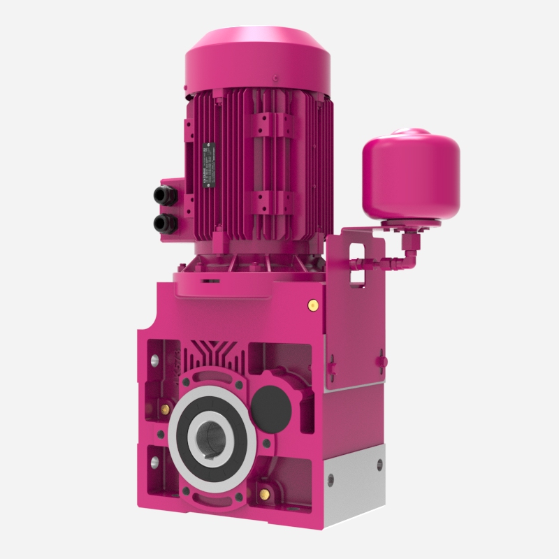
Oil expansion tank
When the gearbox operates in certain mounting positions, the oil level must be very high to lubricate the upper working parts, which can cause oil leaks at high operating speeds. To prevent leaks, an expansion tank is mounted on the gearbox, creating additional space to increase the oil volume inside during operation.
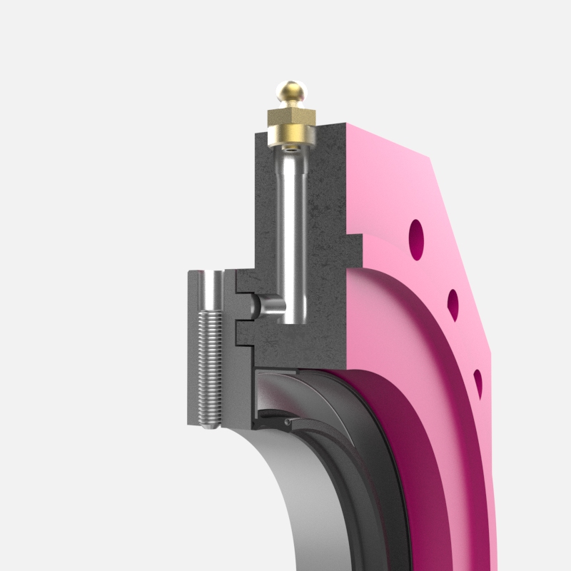
Nilos ring application
Upper bearings that cannot be lubricated by splash lubrication are sealed with metal sheets called Nilos rings. Sealed bearings are lubricated by grease fittings.
Cooling options
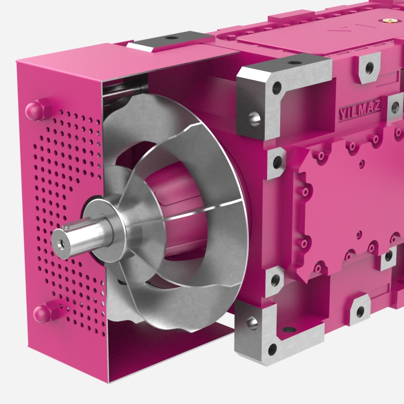
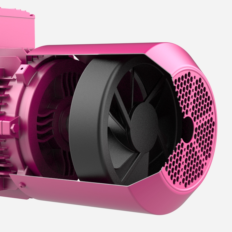
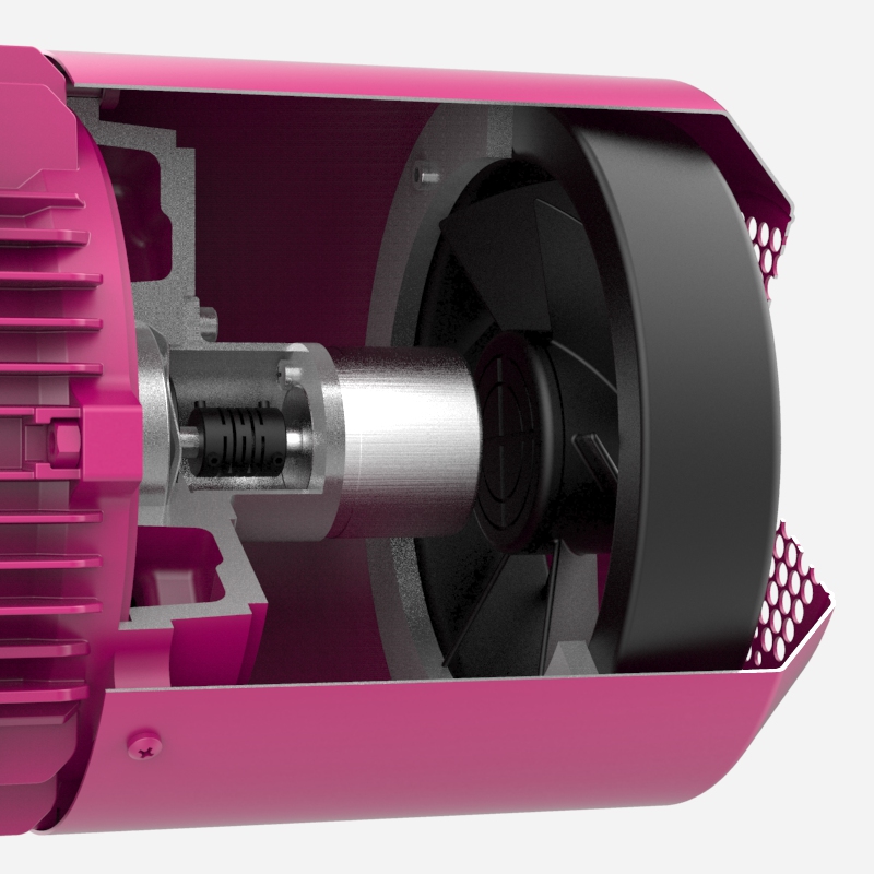
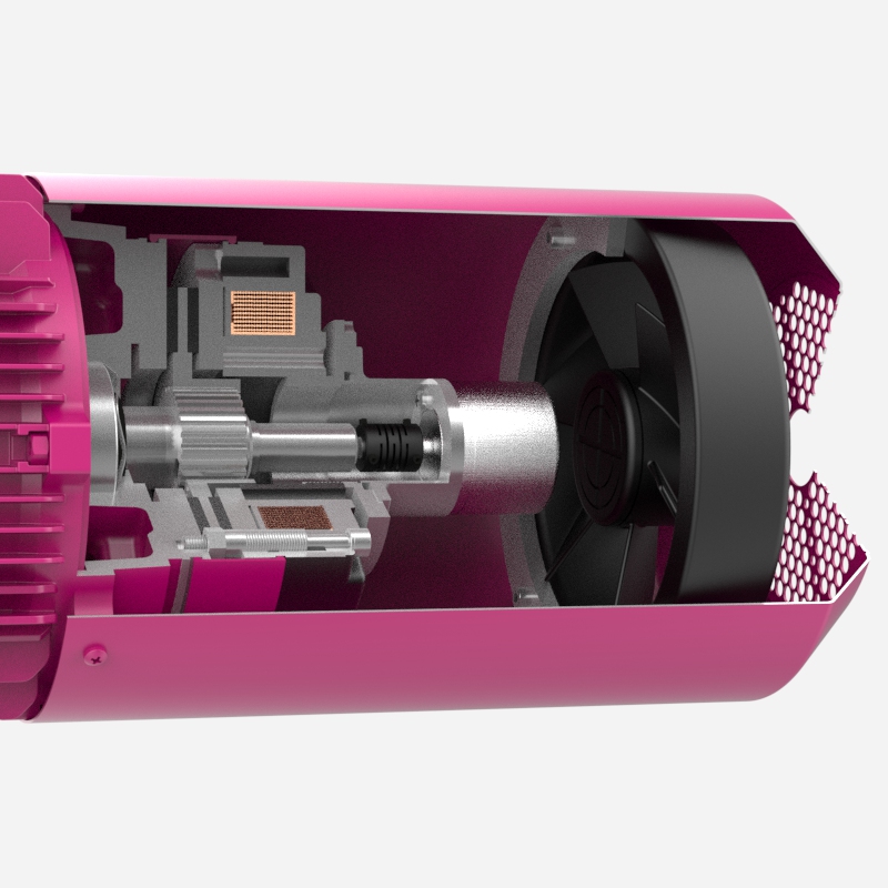
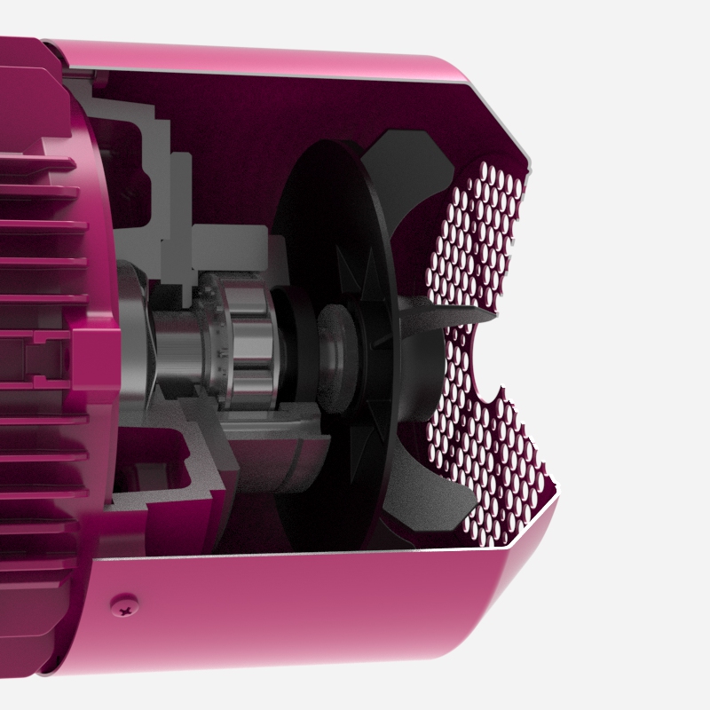
Fan cooling
A cooling fan is mounted on the input shaft to create airflow through the gearbox. This is the most practical cooling option, requiring no cooling water. It is suitable for operating conditions below 40 degrees Celsius and is not suitable for dusty environments.
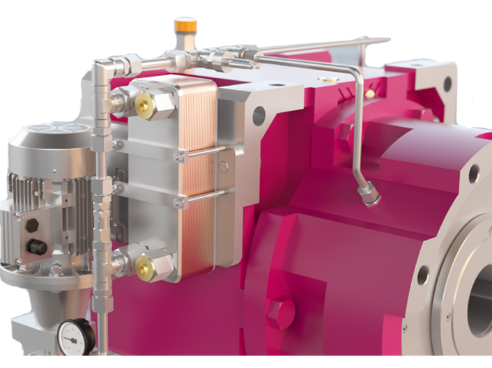
Cooling coil
Cooling is achieved with cold water flowing through copper pipes in the gearbox oil. It requires cold water at a maximum temperature of 30°C. It is suitable for H and B series gearboxes in the M1 mounting position.
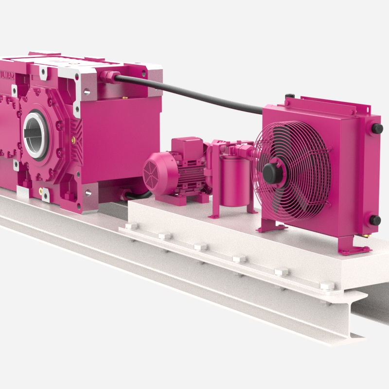
Cooling with air/oil heat exchanger
The cooling system consists of an oil/air heat exchanger, a motor pump, and a filter. The gearbox and cooling system are mounted on a steel frame. It is recommended for ambient temperatures below 40°C and low-dust environments. Another advantage is that it does not require cooling water.
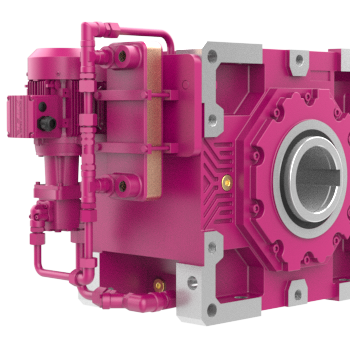
Cooling with oil/water heat exchanger
An oil/water heat exchanger with a pump is mounted on the gearbox. Cooling is achieved via the heat exchanger using cold water. Additional equipment, such as a pressure switch, flow control switch, and pressure gauge, is available as required. It is suitable for all mounting positions.
Braking options
Electromagnetic brakes on the housing
Electromagnetic brakes are mounted on the opposite side of the input shaft in H series gearboxes. They are generally preferred for crane applications as they allow for easy maintenance of the AC motor.
Centrifugal brake
Centrifugal brakes are mounted between the AC motor and the gearbox for added safety in conjunction with the main brake. They stop the AC motor while it is running, using the inertia of the main load that occurs in the event of a main brake failure.
Application of the electromagnetic brake
Eldro brakes are generally preferred for heavy-duty crane applications. They are mounted between the gearbox and the AC motor. We use Eldro brakes on H-series gearboxes if our customer requests it.
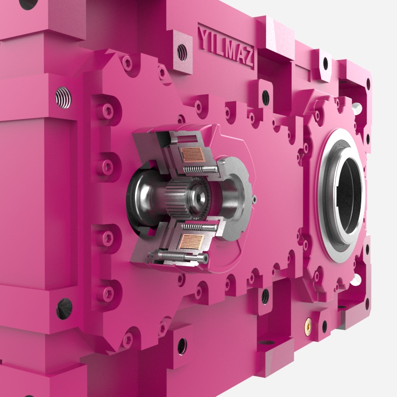
Anti-rotation device

Anti-rotation device on the AC motor shaft
Anti-rollback devices are mounted on the rear cover of the AC motor. They are generally preferred because they are economical and compact.
B5/B14 inlet flange with anti-rotation feature
The anti-rotation device can be supplied inside the new B5/B14 inlet flange which includes two bearings and an elastic coupling.
Anti-rotation device on the housing
The anti-rotation devices are mounted opposite the input shafts of the H series reducers and on the secondary stage shafts of the K and B series reducers.
Torque limiter
Torque limiter
Torque limiters are mounted between the AC motor and the gearbox with a B5 flange. They limit the passing torque to a defined value between the motor and the gearbox. When the torque limit is reached, the proximity sensor sends a signal to stop the motor to prevent damage to the limiter.
Gearboxes with basic chassis
BT Series
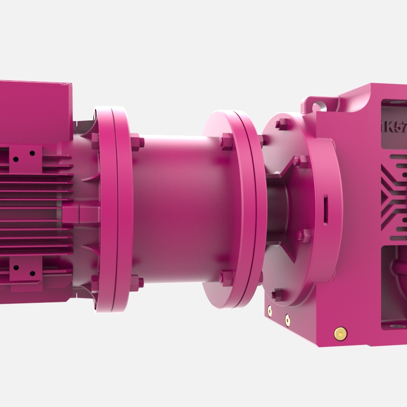
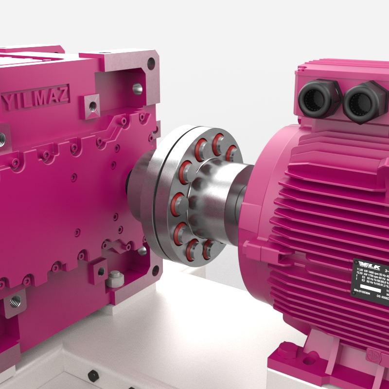
The BT series gearbox, coupling, and foot-mounted AC motor are all mounted on a steel base frame. Couplings can be gear, friction, or hydraulic.
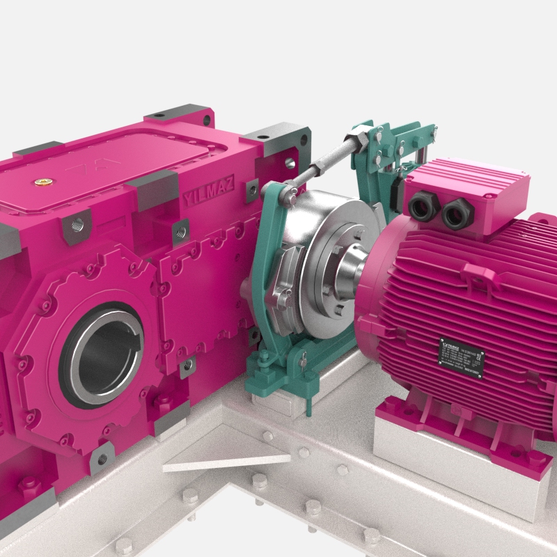
BT series with torque arm
The BT series gearbox with hollow output shaft, coupling, and AC motor with feet are all mounted on a steel frame with a torque arm. The gearboxes are mounted on the shaft of the driven machine with a hollow output shaft, and the frame is shown on the machine base with a torsion arm.
HT Series
The HT series gearbox, coupling, and foot-mounted AC motor are all mounted on a steel base frame. Couplings can be gear, friction, or hydraulic.
Couplings
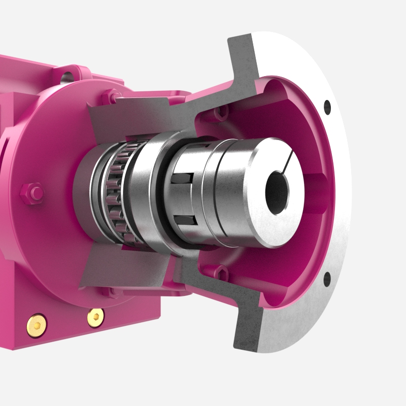
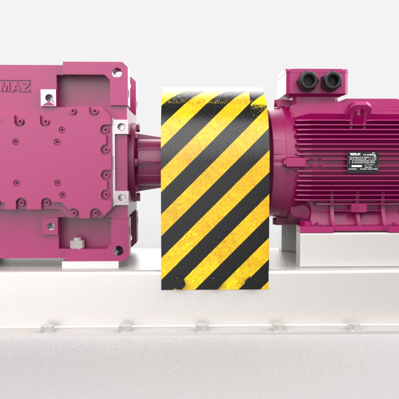
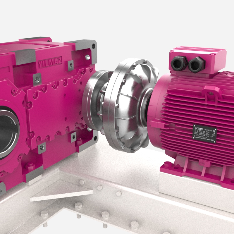
Elastic coupling
It can be used on the input or output shafts of gearboxes. It compensates for shaft misalignment. The coupling housing is made of GS52 steel.
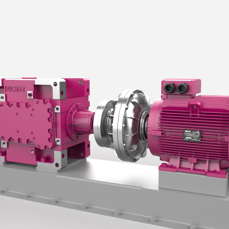
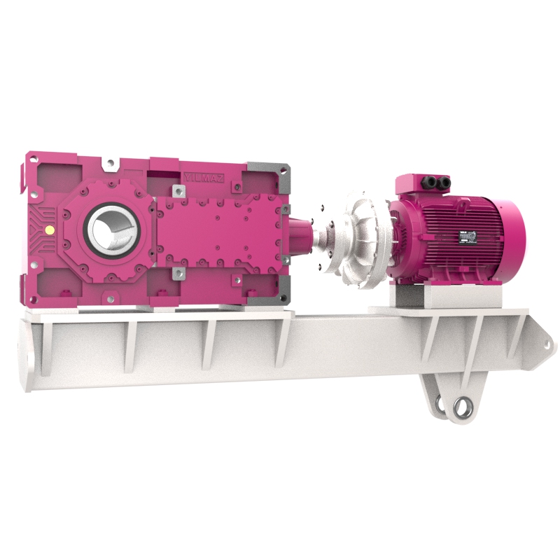
Hydraulic coupling
They are mounted between the AC motor and the gearbox. They are preferred for high inertia applications to allow for a soft start of the motor and to extend the gearbox's lifespan.
Electric motor options
Electromagnetic brakes
Available for all engine sizes. We use electromagnetic brakes from 5 Nm to 1600 Nm with voltages of 24, 230 and 400 volts DC according to customer requirements.
Handbrake
When the electricity is cut off or manual release of the brakes is required, handbrake devices can be used.
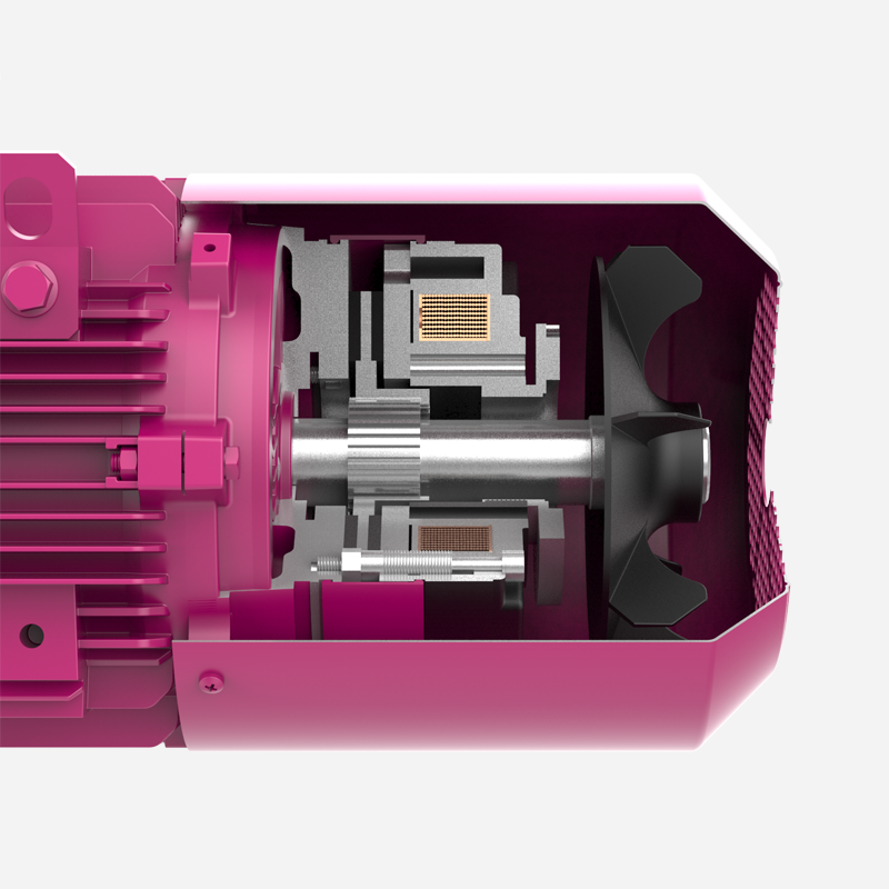
Forced cooling
An additional self-powered fan is required, especially for encoder applications where the motor speed is insufficient for cooling.
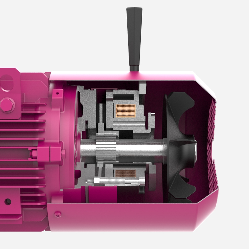
Forced cooling with encoder
If necessary, the encoder and the self-contained fan can be mounted at the rear of the motor, inside the cover, when synchronized operation is essential.
Forced cooling with brake and encoder
If necessary, a brake, an encoder and a self-contained fan can be mounted at the rear of the motor, in the inner cover.
Anti-rotation device
For applications that operate in one direction and whose reverse movement must be stopped, anti-reverse devices are required. These can be mounted inside the motor cover.
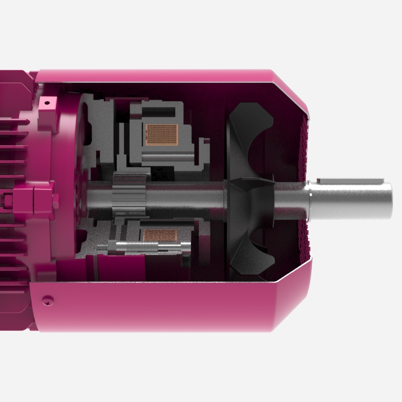
Extension shaft for electric motor
When rear-mounted motor movement is required, or when the motor needs to be rotated manually, an extension shaft can be produced at the rear of the motor.
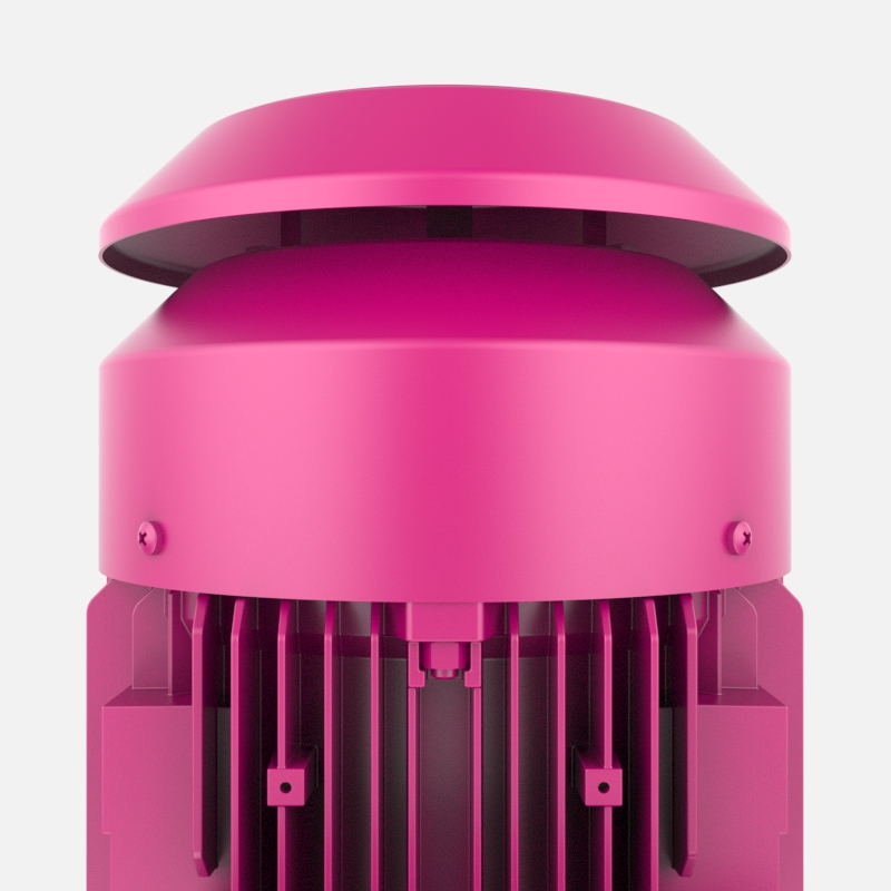
Lid
A cover is available for electric motors that work outdoors to prevent rain from entering the motor.
Protection class
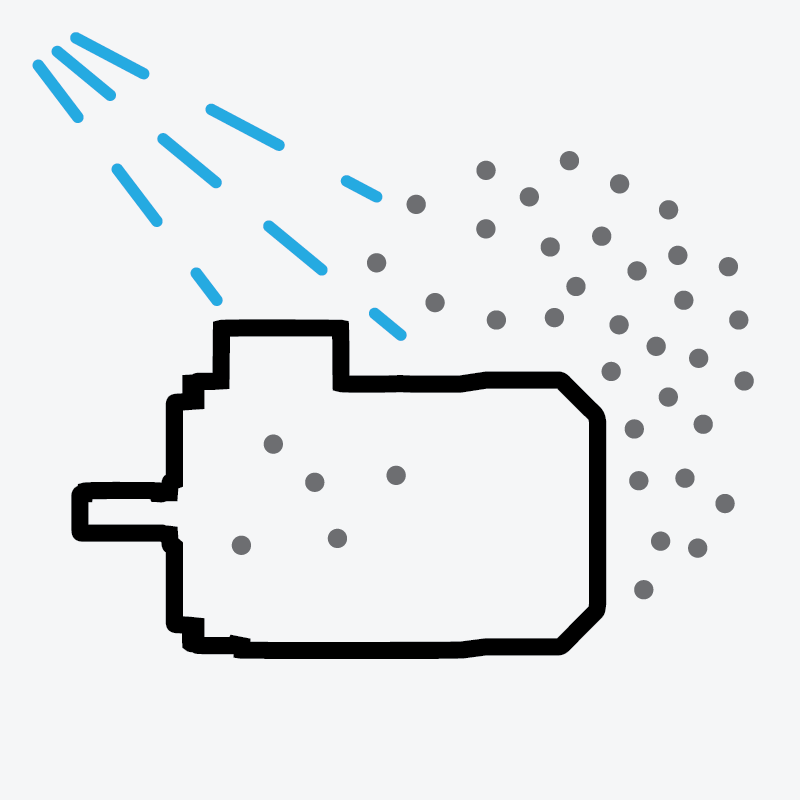
IP55
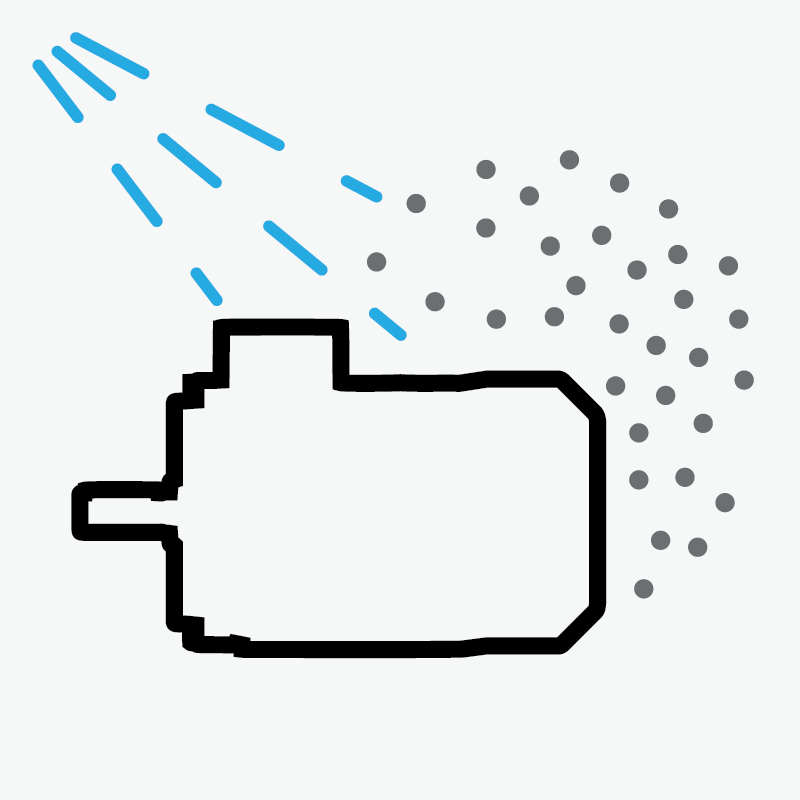
Dust penetration is not completely prevented, but not in sufficient quantities to impair engine operation. Water sprayed from a nozzle against the engine, regardless of its direction, will have no harmful effect.
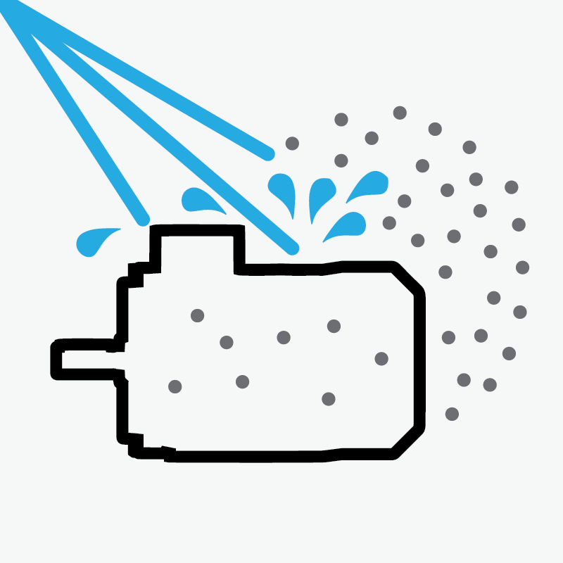
IP56
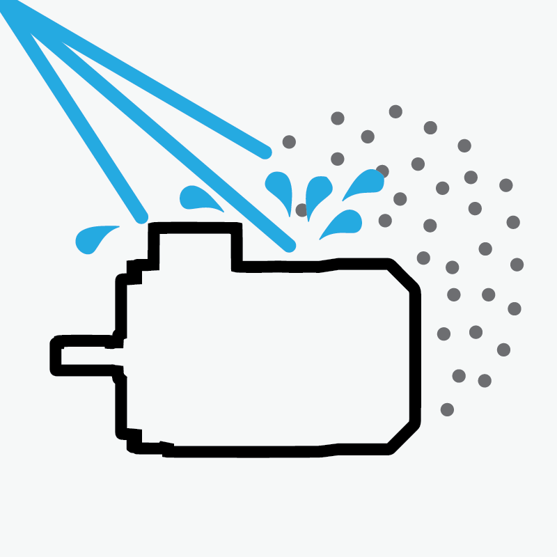
Dust penetration is not completely prevented, but not enough dust enters to impair engine operation. Water from rough seas or powerful jets does not enter the engine in harmful quantities.
IP65
Dust penetration is completely prevented; water projected from a nozzle against the engine, regardless of its direction, will have no harmful effect.
IP66
Dust penetration is completely prevented, and water from a rough sea or water projected by powerful jets does not enter the engine in harmful quantities.
Insulation class

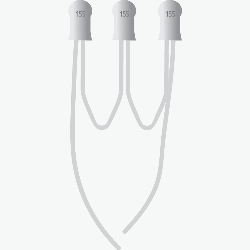
F (Standard)
The standard insulation class of ELK motors is F. The permissible winding temperature is 155°C at an ambient temperature of 40°C.

H
ELK motors can be manufactured in insulation class H. The permissible winding temperature is 180°C at an ambient temperature of 40°C.
Thermal protection
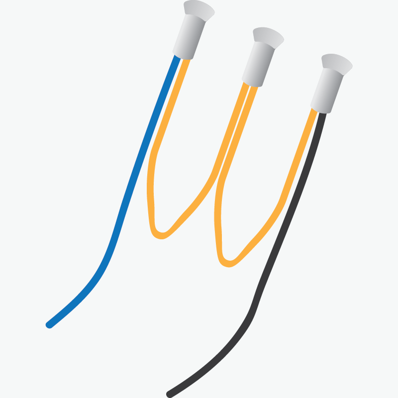
PTC thermistor
When the winding temperature is too high, a thermistor mounted inside the motor winding cuts the circuit and protects the motor from damage.
Thermostat
When the winding temperature is too high, the thermostat mounted inside the motor winding cuts the circuit and protects the motor from damage.
Heaters and drain holes
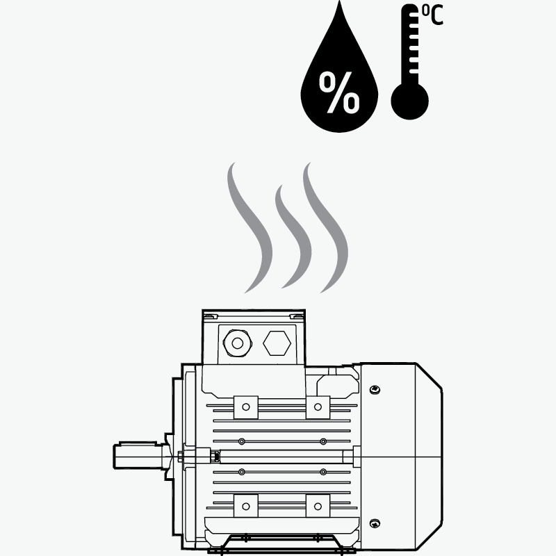
Heaters and drain ports
Water condensation may occur when the motor operates in a very humid environment. To prevent this, heaters are mounted inside the motor to maintain a stable winding temperature. Additionally, drainage holes are provided to prevent water from accumulating within the motor.
Hello! Click below to chat with our team on WhatsApp.